
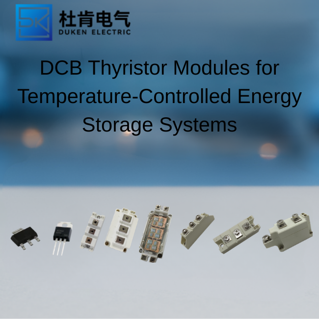
DCB Thyristor Modules for Temperature-Controlled Energy Storage Systems
Author: Selina
An industrial phase control dual thyristor module used in energy storage equipment must handle repeated charge and discharge cycles, high surge current, thermal cycling, and long periods of operation at partial load. In these systems, electrical efficiency and temperature stability are closely connected. A DCB substrate can improve heat spreading and electrical isolation, while low on-state voltage reduces conduction losses. For OEM engineers and procurement managers, the correct module is not simply the one with the highest current rating. Its thermal resistance, surge behavior, gate characteristics, ceramic construction, and production consistency must all match the converter design.
Why Energy Storage Systems Need Robust Phase-Control Devices
Energy storage equipment often includes battery formation systems, industrial battery chargers, discharge test benches, DC load banks, grid-support converters, and temperature-controlled charging cabinets. Many of these systems use thyristor-based phase control because it is rugged, economical, and well suited to high-current AC-to-DC conversion.
In a controlled rectifier, the firing angle determines when each thyristor starts conducting during the AC cycle. Adjusting this angle changes the average DC output voltage and allows the controller to regulate charging current, heating power, or discharge load.
The operating environment can be demanding. A module may experience:
Repetitive current pulses
Transformer inrush current
Battery connection transients
Partial-load operation
Elevated cabinet temperature
Frequent startup and shutdown
Long-duration continuous duty
A high surge current low on-state voltage industrial phase control dual thyristor module is particularly valuable in these conditions. High surge capability protects against short-duration overloads, while low on-state voltage limits heat generation during normal conduction.
The Relationship Between Electrical Loss and Temperature
Thyristor conduction loss can be estimated from the device’s threshold voltage, slope resistance, current waveform, and conduction angle. At high current, a small difference in on-state voltage can produce a meaningful change in thermal load.
For example, if one module has an on-state voltage that is 0.15V lower at 250A, the instantaneous loss reduction is approximately:
P = 0.15V × 250A = 37.5W
In a dual-module assembly operating for thousands of hours per year, this difference can reduce heatsink requirements, cooling energy, and junction-temperature stress.
However, buyers should compare on-state voltage at the intended current and junction temperature. A room-temperature figure may not represent performance inside an operating cabinet.
How DCB Substrates Improve Thermal Performance
A DCB substrate temperature control energy storage high surge current low on-state voltage industrial phase control dual thyristor module uses direct bonded copper construction to combine electrical insulation with efficient thermal transfer.
A typical DCB structure includes:
A copper conductor layer
A ceramic insulation layer
A second copper layer bonded to the opposite side
Semiconductor chips attached to the upper conductor pattern
The copper spreads current and heat, while the ceramic provides dielectric isolation from the module base and heatsink.
Benefits of DCB Construction
DCB substrates are widely used in industrial power modules because they offer several practical advantages:
Good thermal conductivity
High electrical isolation
Low parasitic inductance
Stable mechanical construction
Compact current paths
Compatibility with automated assembly
Strong performance under power cycling
In temperature-controlled energy storage equipment, these benefits help reduce local hot spots. Uniform heat spreading is important because uneven chip temperature can cause current imbalance and accelerate bond-wire or solder fatigue.
Ceramic Material Considerations
Different ceramic materials provide different combinations of thermal conductivity, mechanical strength, and cost. Alumina is widely used because it is economical and electrically reliable. Aluminum nitride offers higher thermal conductivity but usually costs more. Silicon nitride may provide improved mechanical strength and thermal cycling performance in demanding applications.
Procurement teams should not assume that every ceramic-base module performs the same way. They should ask the supplier for substrate material, isolation voltage, thermal resistance, power-cycling data, and allowable baseplate temperature.
Temperature Control and Cooling Design
An industrial phase control dual thyristor module can only deliver its rated current when the cooling system maintains the junction temperature within a safe range. The module, thermal interface material, heatsink, airflow, and ambient conditions must be evaluated as one thermal system.
The junction temperature can be estimated using:
TJ = TC + PLOSS × RθJC
Where:
TJ is junction temperature
TC is module case temperature
PLOSS is semiconductor power loss
RθJC is junction-to-case thermal resistance
This equation is only part of the calculation. The designer must also account for case-to-heatsink resistance and heatsink-to-ambient resistance.
Practical Temperature-Control Measures
For air-cooled systems, engineers should verify fan performance, filter blockage, cabinet recirculation, altitude derating, and maximum ambient temperature. For liquid-cooled systems, coolant temperature, flow rate, corrosion control, and cold-plate flatness must be included.
Temperature sensors should be positioned near the module base or cooling plate. A sensor located far from the power devices may respond too slowly to detect a developing hot spot.
Useful protection functions include:
Overtemperature shutdown
Current derating at high temperature
Fan or pump failure detection
Heatsink temperature alarms
Uneven-phase current monitoring
Cooling-system maintenance reminders
Mounting pressure is also critical. Uneven torque can create air gaps between the module and heatsink, raising thermal resistance. Suppliers should provide mounting torque, surface-flatness requirements, and approved interface-material guidance.
Key Parameters for Model Selection
Purchasing teams should build a comparison table before selecting a module. The most important parameters include:
Voltage Rating
The repetitive peak off-state voltage must provide sufficient margin above the highest expected AC peak and transient voltage. Line variation, transformer leakage, commutation spikes, and switching disturbances should be included.
Current Ratings
Review average current, RMS current, repetitive peak current, and non-repetitive surge current. Current capability depends on cooling conditions and conduction angle, so the headline rating is not enough.
On-State Voltage
Lower on-state voltage reduces conduction loss, but it should be compared at equivalent current and temperature. Characteristic curves are more useful than a single maximum figure.
Surge Current and I²t
The surge rating should be coordinated with semiconductor fuses and upstream protection. I²t data helps determine whether the module can survive a fault long enough for the protection system to clear it.
Gate Characteristics
Gate trigger current, trigger voltage, holding current, and latching current influence the driver circuit. Energy storage equipment often operates in electrically noisy environments, so the driver should provide sufficient trigger margin and noise immunity.
Thermal Resistance
Low junction-to-case thermal resistance supports higher current or a smaller heatsink. However, the full thermal path and cooling system still determine the final junction temperature.
Comparison with Alternative Power Devices
Thyristor modules are not the only option for energy storage power conversion. Engineers may also consider IGBT, MOSFET, bridge rectifier, or SiC-based solutions.
A standard bridge rectifier is simple and economical but does not provide phase-angle output control. It may be suitable when fixed DC output is acceptable.
IGBT converters provide high-frequency PWM control, better dynamic response, and potentially improved power factor. They are useful in bidirectional energy storage systems, but they require more complex gate driving, protection, and control.
MOSFETs are efficient at lower voltages and high switching frequencies, but very high-current industrial systems may require many devices in parallel.
SiC modules can reduce switching losses and support higher operating temperature. Their purchase cost and EMI requirements may be higher, and they may not be necessary for line-frequency or low-frequency phase-control applications.
For high-current controlled rectification, the industrial phase control dual thyristor module remains attractive because of its low conduction loss, high surge tolerance, simple gate control, and proven field reliability.
Supplier Qualification and Application Testing
A technically suitable module can still create production risk if the supplier lacks traceability or process control. Buyers should request:
Electrical characteristic curves
DCB and ceramic material information
Thermal resistance data
Surge-current test conditions
Power-cycling results
Isolation-voltage test data
Mechanical drawings
Mounting instructions
Lot traceability
RoHS and REACH documentation
Process-change notification procedures
Samples should be tested under realistic conditions. Recommended tests include full-load operation, repeated charge and discharge cycles, high-temperature operation, surge-current testing, firing-angle sweeps, thermal imaging, and cooling-failure simulation.
Incoming inspection should verify dimensions, terminal quality, baseplate flatness, markings, isolation, gate behavior, and forward voltage. For long-term programs, an approved specification should define acceptable electrical and mechanical limits.
Conclusion
A DCB-based industrial phase control dual thyristor module can provide reliable current regulation in battery charging, energy storage testing, DC load control, and industrial temperature-management systems. The strongest design combines low on-state voltage, high surge capability, efficient ceramic insulation, controlled mounting, and an adequate cooling system. Procurement teams should evaluate thermal performance, gate characteristics, protection coordination, and supplier quality together rather than selecting by current rating alone.
FAQ
1. Why is DCB construction useful in energy storage equipment?
DCB substrates combine electrical isolation with effective heat spreading, helping reduce hot spots and support reliable high-current operation.
2. Does low on-state voltage always mean the module is more efficient?
Usually it reduces conduction loss, but total system efficiency also depends on current waveform, conduction angle, cooling, transformer losses, and control strategy.
3. How much voltage margin should a thyristor module have?
The required margin depends on the AC supply, transformer, transient environment, and protection network. The actual peak voltage should be measured before final selection.
4. Can a thyristor module be used in a bidirectional battery converter?
A conventional phase-controlled thyristor system may support controlled rectification and, in certain topologies, inversion. Fully bidirectional modern systems often use IGBT or SiC converters for greater control flexibility.
5. What should be tested before volume purchasing?
Buyers should verify thermal performance, surge behavior, gate triggering, isolation, forward voltage, power cycling, mounting quality, and operation under cooling faults.
READ MORE:
300A Phase Control Thyristor vs IGBT, SiC, and Rectifier Solutions
Using 6500 V 300A Phase Control Thyristors in Large-Scale Heating Systems
Selecting a KP300A-6500V Thyristor for High-Voltage AC Power Regulators
Forced-Cooling Heat Sink Design for 300A Thyristors in Mining Equipment
Harmonics and Power Factor in Phase-Controlled Thyristor Systems
How to Read a 300A Phase Control Thyristor Datasheet for Industrial Power Systems